Boundary Layers
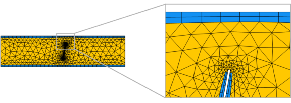
A Boundary Layers mesh () is a mesh with dense element distribution in the normal direction along specific boundaries, as shown in Figure 8-27. This type of mesh is typically used for fluid flow problems to resolve the thin boundary layers along the no-slip boundaries.
Figure 8-27: A channel in which a fluid flows from the left to the right and is hindered by a tilted blade in the middle of the channel. A boundary layer mesh is added to the wall boundaries (blue quad elements) to resolve the regions closest to the no-slip boundaries. The image to the left shows the full geometry while the image on the right hand side shows a smaller portion of the geometry, zoomed in on the top of the blade.
Additional elements of an arbitrary type can also be inserted into the layers if needed.
In 3D, for a mesh that defines its own geometric model, it is possible to create a boundary layer mesh in meshed domains. If the selected domains are not meshed, use a Free Tetrahedral operation to add a volume mesh before building the Boundary Layers node.
See The Mesh Node to learn more about meshes that define their own geometric model.
To create a boundary layer mesh, select boundaries (2D and 3D) or edges (for a boundary layer mesh on boundaries in 3D) in the graphics, then:
Right-click in the Graphics window and select Boundary Layers () from the menu. For more information, see The Graphics Context Menu.
On The Mesh Toolbar click the Boundary Layers button ().
In the Mesh ribbon toolbar (Windows) or from the Mesh contextual toolbar (macOS and Linux), click the Boundary Layers button ().
Right-click a 2D or 3D Mesh node and select Boundary Layers.
Then enter the properties for the boundary layer mesher using the following sections:
Geometric Entity Selection
Specify the entities where a boundary layer mesh will be created by first choosing an option from the Geometric entity level list:
Choose Entire geometry to specify boundary layer mesh for the entire geometry.
Choose Domain to specify the domains for which you want a boundary layer mesh. Choose Manual in the Selection list to select the domains in the Graphics window, choose a named selection to refer to a previously defined selection, or choose All domains to select all domains.
Choose Boundary (available in 3D only) to select boundaries for which to generate a boundary layer mesh along its edges. Choose Manual in the Selection list to select the boundaries in the Graphics window, choose a named selection to refer to a previously defined selection, or choose All boundaries to select all boundaries. Use a Swept operation to sweep the face mesh in adjacent domains to create a volumetric boundary layer mesh.
Corner Settings
The following options for handling boundary layers at sharp corners are available from the Handling of sharp corners list (in 2D) and the Handling of sharp edges list (3D):
Select Splitting (the default) to introduce boundary layer splits at sharp corners, as shown in Figure 8-28. In the Minimum angle for splitting field you specify the minimum angle between adjacent boundary layer boundaries for a split to occur. Control the maximum angle of the elements in the split region by the Maximum angle per split parameter.
Select Trimming to trim the boundary layer mesh at sharp corners. In the Minimum angle for trimming field you specify the minimum angle between adjacent boundary layer boundaries for trimming to occur. It is recommended to combine Trimming with a Corner Refinement node to refine the mesh further close to the sharp corner, as shown in Figure 8-28.
Select No special handling to not use any special treatment at sharp corners, as shown below.
Figure 8-28: The different options for handling sharp corners: Splitting, Trimming with Corner Refinement applied, and No special handling.
In the Maximum layer decrement field you can specify the maximum difference in number of boundary layers between neighboring points on boundary layer boundaries.
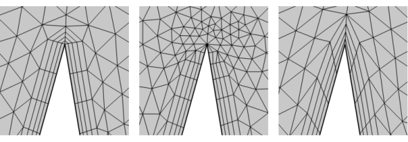
In the section Trimming in narrow corners, specify the Maximum angle for trimming. This setting controls the maximum angle between adjacent boundaries for trimming to occur, as shown in Figure 8-29. For angles between a boundary layer boundary and any other boundary, half the Maximum angle for trimming is used.
Figure 8-29: The boundary layer mesh in a 45 degree corner. With the Maximum angle for trimming set to 50 degrees, the corner is considered as narrow and trimming occurs. Setting the value to 40 degrees, avoids trimming in the corner.
Transition
Select the Smooth transition to interior mesh check box to smooth the transition in element size from the boundary layer mesh to the interior mesh. You can specify the number of smoothing iterations in the Number of iterations field. In the Maximum element depth to process field you can specify the maximum element depth, from the boundary layer interface, for the mesh points to be smoothed.
When a Boundary Layers node is added, a Boundary Layer Properties node is automatically added as a subnode. Use this subnode to specify the boundary layers and the properties of the boundary layers. If you want to specify different boundary layer properties for more than one boundary selection, right-click the Boundary Layers node and add additional Boundary Layer Properties subnodes. However, adjacent boundaries must have the same number of boundary layers.
For a 2D boundary layer mesh, see Soluble Lead–Acid Redox Flow Battery (2D):
Application Library path Battery_Design_Module/Flow_Batteries/pb_flow_battery.
For a 2D tutorial, see Turbulent Flow over a Backward-Facing Step (2D):
Application Library path CFD_Module/Verification_Examples/turbulent_backstep.
For a 3D boundary layer mesh, see Turbulent Flow over a Backward-Facing Step:
Application Library path Heat_Transfer_Module/Verification_Examples/turbulent_backstep.
For a 3D tutorial, see Low Temperature PEM Fuel Cell with Serpentine Flow Field: Application Library path Fuel_Cell_and_Electrolyzer_Module/Fuel_Cells/pemfc_serpentine_flow_field.
For a boundary layer mesh built in a remeshed STL mesh, see
Analyzing Porous Structures on the Microscopic Scale: Application Library path Porous_Media_Flow_Module/Fluid_Flow/pore_scale_flow_3d.