Swept
The Swept node () creates a swept mesh on a domain in 3D by sweeping the mesh from the source faces along the domain to the opposite destination faces, as shown in Figure 8-68. A swept mesh is an example of a semistructured mesh since it is structured in the sweep direction and can be either structured or unstructured orthogonally to the direction of the sweep. A swept mesh is typically a hexahedral mesh (hex mesh) or a prism mesh.
Figure 8-68: Generation of a hexahedral mesh. A mapped mesh is built on the source face, highlighted in blue. This mesh is swept along the circular linking edges (highlighted in red), resulting in a hexahedral mesh, as shown to the right.
The Swept operation is available both for meshing sequences that generate mesh for a geometry and for meshes that define their own geometric model.
See The Mesh Node for more information about meshes that define their own geometric models.
You can control the number, size, and distribution of elements using the Size and Distribution subnodes. The Swept operation only reads properties from Size nodes defined on the entire geometry or on the domain level and Distribution nodes defined on the domain level.
Classifications
Each face about a domain that is to be operated on by the swept mesher is classified as either a source face, a destination face, or a linking face. The linking faces are the faces connecting the source and destination faces (see Figure 8-69).
The linking edges are the edges, or the chains of edges, connecting the source and destination faces.
Figure 8-69: Classification of the boundaries and edges about a domain used for swept meshing. Two faces in the foreground are hidden for visibility.
Requirements
For the sweeping technique to work, the geometry must satisfy these criteria:
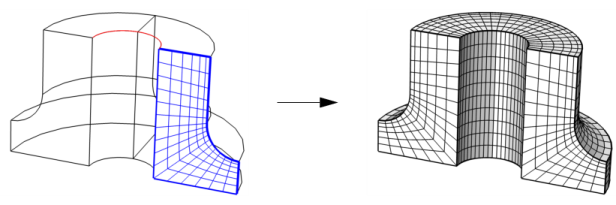
Each source face must correspond to precisely one destination face or a subset of it (see Figure 8-70). If needed, use a Cross Section operation to make an imprint of the source faces on the destination.
Figure 8-70: Determination of sweep direction. If the number of faces differ on source and destination, the source will always have the larger number of faces.
Even if the original geometry does not fulfill the above criteria, it is sometimes possible to partition the geometry in order to obtain domains where a swept mesh can be created.
If any of the faces about a domain is meshed prior to the sweeping operation, the following must be fulfilled:
The swept mesher can handle domains with multiple linking faces in the sweep direction, as seen in Figure 8-70.
To create a swept mesh, select the domains to sweep or the boundaries to use as source faces in the Graphics window, then :
In the Mesh toolbar, click the Swept () button.
Right-click a 3D Mesh node and select Swept.
Domain Selection
Specify the domains where you want a swept mesh. Choose the level of the geometry from the Geometric entity level list:
Choose Remaining to generate a swept mesh for the remaining, unmeshed domains.
Choose Entire geometry to specify swept mesh for the entire geometry.
Choose Domain to specify the domains for which you want a swept mesh. Choose Manual in the Selection list to select the domains in the Graphics window, choose a named selection to refer to a previously defined selection, or choose All domains to select all domains.
Source Faces
Click the Activate Selection button to toggle between turning ON and OFF selections.
In most cases the swept mesher can automatically identify source and destination faces from the geometry. To specify the source faces directly, activate the Source Faces list and select the faces defining the source of the sweep operation in the Graphics window.
Click the Swap Source and Destination button () to swap the faces in the source list above and the faces in the destination list in the Destination Faces section below.
Destination Faces
To specify the destination faces directly, activate the Destination Faces list and select the faces defining the destination of the sweep operation in the Graphics window.
Sweep Method
Face Meshing Method
In the Face meshing method list, you can specify how unmeshed source faces are automatically meshed by the Swept operation. For meshes defining their own geometric model, select the Remesh source faces check box (selected by default) to remesh the source faces using the selected method:
Select Quadrilateral (generate hexahedra) to generate a surface mesh with quadrilateral elements. This is the default meshing method.
Select Triangular (generate prisms) to generate a surface mesh with triangular elements.
Sweeping Path
Use the Swept path calculation list if you want to specify the shape of the sweep path:
The default, Automatic, means that the sweeping algorithm automatically tries to determine if the sweep path is straight or circular; otherwise, a general approach is used.
Sweep following straight lines means that all interior mesh points are located on straight lines between the corresponding source and destination points.
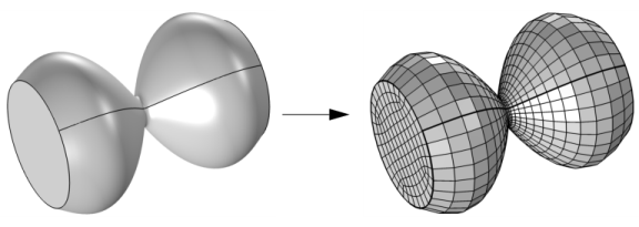
Sweep following circular arcs means that all interior mesh points are located on circular arcs between the corresponding source and destination points, as shown in Figure 8-68.
Sweep using interpolation means that the positions of the interior mesh points are determined by a general interpolation procedure, as shown in Figure 8-71.
Figure 8-71: An hourglass-shaped geometry in which an unstructured quad mesh is swept using a general interpolation procedure.
Destination Mesh
Use the Destination mesh generation list if you want to specify the method to be used for transferring the source mesh to the destination:
The default, Determine suitable method, means that the algorithm automatically tries to determine a suitable method for creating the destination mesh.
Use a rigid transformation when the source and destination have the same shape, up to a scaling factor.
Morph source onto destination when the source and destination have different shape. For example, when going from a circular to a rectangular cross-section, or going from a planar source face to a curved destination face.
Project source mesh onto destination means that the destination mesh is created from the source mesh by a projection technique. This is useful when the source and destination faces are close to each other and have different shape.
Control Entities
Select the Smooth across removed control entities check box to smooth the transition in element size across removed control entities. When selected, the mesher adjusts the sizes of the mesh elements to get a smoother transition from large to small elements by adjusting the locations of the mesh vertices on the entity that is removed. Clear the check box to not adjust the mesh. You can specify the number of smoothing iterations in the Number of iterations field. In the Maximum element depth to process field you can specify the maximum element depth for the mesh points to be smoothed.
Figure 8-72: Comparing meshes where Smooth across removed control entities has been used vs. not used.
Linking Faces
You can choose between two different interpolation methods for the linking faces in the Interpolation method for linking faces list. This specifies how the mapped mesher, which is used by the swept mesher for the linking faces, determines the positions of the interior mesh points. For more information on the different options see Mapped.
Swept Meshing of a Bracket Geometry:
Application Library path COMSOL_Multiphysics/Meshing_Tutorials/bracket_swept_mesh.
Using Meshing Sequences:
Application Library path COMSOL_Multiphysics/Meshing_Tutorials/meshing_sequence.
Laser Heating of a Silicon Wafer:
Application Library path COMSOL_Multiphysics/Heat_Transfer/laser_heating_wafer.
Deformation of a Feeder Clamp:
Application Library path COMSOL_Multiphysics/Structural_Mechanics/feeder_clamp.
Joule Heating of a Microactuator:
Application Library path COMSOL_Multiphysics/Multiphysics/thermal_actuator_jh.