Free Tetrahedral
The operation creates an unstructured tetrahedral mesh on a selection of domains, as shown in Figure 8-46. If no selection is specified, Free Tetrahedral creates a mesh on the remaining domains, boundaries, edges and points. It inserts pyramids to match the tetrahedral mesh to any existing quad mesh on adjacent faces.
Figure 8-46: An unstructured mesh of a golf club and ball (left), created by the Free Tetrahedral operation. The image is accomplished by filtering out some elements in a Mesh plot. The image to the right pictures a tetrahedral mesh (green) where pyramids (magenta) are inserted to match to an existing quad mesh (blue) on the face of a bent pipe. Some elements have been filtered out and the remaining volume elements are shrunk with a factor 0.8.
The Free Tetrahedral operation is available both for meshing sequences that generate mesh for a geometry and for meshes that define their own geometric model.
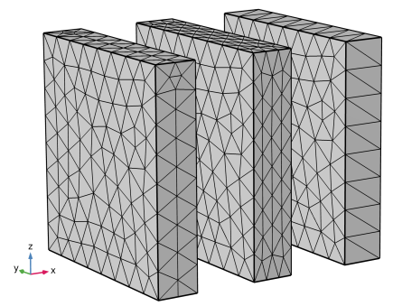
See The Mesh Node for more information about meshes that define their own geometric models.
When you generate a mesh for a geometry, you can control the number, size, and distribution of elements by using one or several Size, Size Expression, Distribution, and Corner Refinement attributes.
For meshes that define their own geometric model, the Free Tetrahedral () node has a default Size subnode which, in practice, defines the size on the same selection as for the parent node. This subnode cannot be deleted or disabled. You can add more Size attributes to further control the element size.
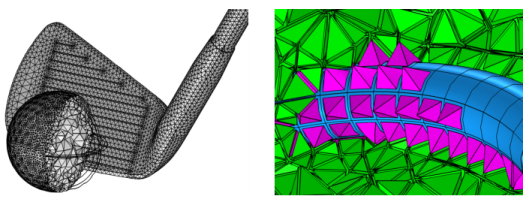
Refer to the section Remeshing Imported Meshes for more information and related tutorials.
To create an unstructured tetrahedral mesh, select one or several domain in the Graphics menu, then:
In the Mesh toolbar click the Free Tetrahedral () button.
Right-click a Mesh node and choose Free Tetrahedral.
Then define the properties for the tetrahedral meshing operation using the following sections:
Domain Selection
Define the domains where you want to create an unstructured tetrahedral mesh. Choose the level of the geometry from the Geometric entity level list:
Choose Remaining to specify unstructured tetrahedral mesh for remaining, unmeshed domains.
Choose Entire geometry to create an unstructured tetrahedral mesh in the entire geometry.
Choose Domain to specify the domains for which you want to create an unstructured tetrahedral mesh. Choose Manual in the Selection list to select the domains in the Graphics window, choose a named selection to refer to a previously defined selection, or choose All domains to select all domains.
Scale Geometry
To scale the geometry during the meshing operation, change the x-scale, y-scale, and z-scale to positive real numbers, as done for the mesh in Figure 8-47. If any of the scale factors are not equal to one (1), the software scales the geometry in those directions before meshing. After meshing, it restores the geometry and mesh to fit the original size.
Figure 8-47: Three thin blocks with unstructured tetrahedral meshes. The first block (to the left) has no scaling applied. The geometry of the middle block is scaled with a factor 2 in the x direction and the last block (to the right) with a factor 0.5 in the x direction before they are meshed and restored back to their original size.
The scale factors make it possible to generate meshes that are anisotropic, and they are useful if the mesh generator creates many elements due to a thin geometry or if the mesh generation fails due to large aspect ratios in the geometry. Compare this to changing the Resolution of narrow region parameter in a mesh Size attribute to only affect the mesh size in narrow regions. Another alternative is using a Swept mesh operation for the thin parts of a geometry. The resulting hexahedral or prism elements usually have better element quality compared to the unstructured mesh after scaling the geometry. Consider using Remove Details to remove narrow face regions and thin domains, if not important to the simulation at hand. Yet another possibility is to simplify the geometry by using shell approximations in the physics, where appropriate.
Control Entities
Select the Smooth across removed control entities check box to smooth the transition in element size across removed Controlling the Mesh Size Using Mesh Control Entities. You can specify the number of smoothing iterations in the Number of iterations field. In the Maximum element depth to process field you can specify the maximum element depth for the mesh points to be smoothed.
Figure 8-48: Comparing meshes where Smooth across removed control entities has been used vs. not used. With the Smooth across removed control entities check box selected, the mesher adjusts the sizes of the mesh elements to get a smoother transition from large to small elements by moving the mesh vertices. Clear the check box to not adjust the mesh.
Tessellation
From the Method list, choose the Delaunay tessellation method to use for creating a tetrahedral mesh:
Select Automatic (the default) to make the mesh generator determine the best algorithm to use for each domain.
Select Delaunay to use a version of the Delaunay algorithm that under some conditions can modify the boundary mesh to simplify the meshing.
Select Delaunay (legacy version) to use the Delaunay algorithm available in earlier versions of COMSOL Multiphysics. This is also the method that will be used if you open a model created in COMSOL Multiphysics 5.1 or earlier.
Element Quality Optimization
In this section, you can control how much effort COMSOL Multiphysics puts into optimizing the minimum element quality and tuning the optimization for certain situations. Use the Mesh Statistics to see the full statistics of your mesh. All optimization is done on the volume elements while keeping the surface mesh fixed.
From the Optimization level list, choose one of the following levels:
Basic (the default), which makes basic optimizations aiming at a minimal element quality of 0.2.
Medium, which makes more optimization and aims at a minimal element quality of 0.35. Meshing with medium level will take longer time than with the Basic level.
High, which attempts all available optimization operations. If the quality of the mesh is low, meshing with this setting can take a significant amount of time.
As an example, refer to the tutorial Adjusting the Element Size for the Unstructured Mesh Generator and compare the amount of mesh elements plotted for qualskewness < 0.2 (see Figure 8-49). In this tutorial, the Maximum element growth rate is high which means that the element size can grow fast from the small elements on the boundaries into the domain. This results in fewer domain elements, but also more elements of less good quality. Increasing the Optimization level from Basic (image 2 below) to High (image 3 below) increases both the minimum and average quality. Compare this to lowering the Maximum element growth rate (image 4), which gives about the same minimum and average quality, but results in more elements in total.
Figure 8-49: Comparing the meshes built with different Optimization level settings and compared to a mesh with finer size settings. 1. The mesh of the piston. 2. A plot of the mesh built with Optimization lever: Basic. 3. Mesh built with Optimization level: High. Optimizing the mesh influences the elements some distance away, which is why new elements may appear. 4. A mesh built with lowered Maximum element growth rate on the domain. About the same quality as (3), but this mesh has three times as many elements.
There are additional settings under Accept lower element quality to that you can use if you can accept a lower mesh element quality. A Physics-Controlled Mesh will typically ensure that the mesh is good with respect to the physics at hand and is recommended. For user-controlled meshing sequences, wave and CFD problems are examples of computations that can be sensitive to too large and too small elements and may require changed settings.
If the computation is sensitive to too large mesh elements, you can select the Avoid too large elements check box. For each mesh element, there is a desired element size (h), specified by the mesh size parameters, and if the element is larger than that, COMSOL Multiphysics tries to make it smaller. The cost for this option is longer meshing time and a lower element quality. If you evaluate the maximum of h on a sufficiently large mesh of uniform size, this value is typically decreased by 10 percent if you have selected this option.
Select the Avoid too small elements check box to optimize the mesh so that the diameter of the inscribed sphere of each element is maximized while still trying to respect the desired local element size. Optimizing this parameter can improve performance when solving problems using the discontinuous Galerkin method. Refer to the section The Time-Explicit Algorithms for more information.
The Avoid inverted curved elements check box is selected by default. This setting makes the optimization try to reduce the number of mesh elements that become inverted when they are curved. The cost of this optimization is longer meshing time, often a slightly higher number of mesh elements, and a lower element quality.
For a tutorial about how to change the mesh size parameters to adjust the elements size, see
Adjusting the Element Size for the Unstructured Mesh Generator:
Application Library path COMSOL_Multiphysics/Meshing_Tutorials/piston_mesh.
For a tutorial of a mesh with only tetrahedral elements, see Hepatic Tumor Ablation:
Application Library path Heat_Transfer_Module/Medical_Technology/tumor_ablation.
For a tutorial of a mixed tetrahedral and swept mesh, see
Anisotropic Heat Transfer Through Woven Carbon Fibers: Application Library path Heat_Transfer_Module/Tutorials,_Conduction/carbon_fibers_infinite_elements.
For a tutorial about using the operation on an imported surface mesh, see
STL Import 2 — Remeshing an Imported Mesh:
Application Library path COMSOL_Multiphysics/Meshing_Tutorials/stl_vertebra_mesh_import.