
| 
                1	
               | 
| 
                2	
               | 
| 
                3	
               | Click Add. | 
| 
                4	
               | Click   Study. | 
| 
                5	
               | 
| 
                6	
               | Click   Done. | 
| 
                1	
               | 
| 
                2	
               | 
| 
                1	
               | 
| 
                2	
               | Browse to the model’s Application Libraries folder and double-click the file magnetic_lens_geom_sequence.mph. | 
| 
                1	
               | 
| 
                2	
               | 
| 
                3	
               | In the tree, select Built-in>Copper. | 
| 
                4	
               | 
| 
                5	
               | 
| 
                6	
               | 
| 
                7	
               | 
| 
                1	
               | In the Model Builder window, under Component 1 (comp1) right-click Magnetic Fields (mf) and choose the domain setting Coil. | 
| 
                3	
               | 
| 
                4	
               | 
| 
                5	
               | 
| 
                6	
               | 
| 
                7	
               | 
| 
                1	
               | 
| 
                2	
               | 
| 
                3	
               | 
| 
                1	
               | 
| 
                2	
               | 
| 
                3	
               | 
| 
                5	
               | 
| 
                1	
               | 
| 
                1	
               | 
| 
                2	
               | 
| 
                3	
               | 
| 
                1	
               | 
| 
                2	
               | 
| 
                1	
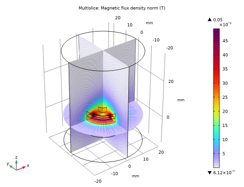
               | In the Model Builder window, expand the Magnetic Flux Density Norm (mf) node, then click Multislice 1. | 
| 
                2	
               | 
| 
                3	
               | 
| 
                1	
               | 
| 
                2	
               | 
| 
                3	
               | 
| 
                4	
               | 
| 
                5	
               | 
| 
                1	
               | 
| 
                2	
               | 
| 
                3	
               | 
| 
                4	
               | Find the Physics interfaces in study subsection. In the table, clear the Solve check box for Study 1. | 
| 
                5	
               | 
| 
                6	
               | 
| 
                1	
               | 
| 
                2	
               | 
| 
                3	
               | 
| 
                4	
               | Find the Physics interfaces in study subsection. In the table, clear the Solve check box for Magnetic Fields (mf). | 
| 
                5	
               | 
| 
                6	
               | 
| 
                1	
               | 
| 
                2	
               | 
| 
                3	
               | 
| 
                1	
               | In the Model Builder window, under Component 1 (comp1)>Charged Particle Tracing (cpt) click Particle Properties 1. | 
| 
                2	
               | 
| 
                3	
               | 
| 
                1	
               | 
| 
                2	
               | 
| 
                3	
               | 
| 
                4	
               | 
| 
                1	
               | 
| 
                3	
               | 
| 
                4	
               | 
| 
                5	
               | 
| 
                6	
               | 
| 
                1	
               | 
| 
                2	
               | In the Settings window for Time Dependent, click to expand the Values of Dependent Variables section. | 
| 
                3	
               | Find the Values of variables not solved for subsection. From the Settings list, choose User controlled. | 
| 
                4	
               | 
| 
                5	
               | 
| 
                6	
               | 
| 
                7	
               | 
| 
                8	
               | 
| 
                9	
               | 
| 
                10	
               | Click Replace. | 
| 
                11	
               | 
| 
                1	
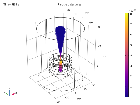
               | In the Model Builder window, expand the Results>Particle Trajectories (cpt)>Particle Trajectories 1 node, then click Particle Trajectories 1. | 
| 
                2	
               | 
| 
                3	
               | 
| 
                4	
               | 
| 
                1	
               | 
| 
                2	
               | 
| 
                3	
               | 
| 
                4	
               | 
| 
                5	
               | 
| 
                6	
               | Click OK. | 
| 
                7	
               | 
| 
                1	
               | 
| 
                2	
               | In the Settings window for 3D Plot Group, type Average Beam Position and Hyperemittance in the Label text field. | 
| 
                1	
               | In the Model Builder window, expand the Average Beam Position and Hyperemittance node, then click Point Trajectories 1. | 
| 
                2	
               | 
| 
                3	
               | 
| 
                4	
               | Click the  button. From the menu, choose Component 1 (comp1)>Charged Particle Tracing>Beam properties>cpt.e1hrms - 1-RMS beam hyperemittance - m². | 
| 
                5	
               | 
| 
                6	
               | 
| 
                7	
               | 
| 
                1	
               | 
| 
                2	
               | 
| 
                3	
               | 
| 
                4	
               | 
| 
                5	
               | 
| 
                1	
               | 
| 
                2	
               | 
| 
                3	
               | 
| 
                1	
               | 
| 
                2	
               | 
| 
                3	
               | 
| 
                1	
               | 
| 
                2	
               | 
| 
                3	
               | 
| 
                4	
               | 
| 
                1	
               | 
| 
                2	
               | 
| 
                3	
               | 
| 
                4	
               | 
| 
                5	
               | 
| 
                6	
               | 
| 
                1	
               | 
| 
                2	
               | 
| 
                3	
               | 
| 
                4	
               | 
| 
                1	
               | 
| 
                2	
               | 
| 
                3	
               | 
| 
                4	
               | 
| 
                5	
               | 
| 
                1	
               | 
| 
                2	
               | 
| 
                1	
               | 
| 
                2	
               | 
| 
                3	
               | 
| 
                4	
               | 
| 
                1	
               | 
| 
                2	
               | 
| 
                3	
               | 
| 
                4	
               | 
| 
                5	
               | 
| 
                1	
               | In the Model Builder window, under Component 1 (comp1)>Geometry 1 right-click Cylinder 1 (cyl1) and choose Duplicate. | 
| 
                2	
               | 
| 
                3	
               | 
| 
                1	
               | 
| 
                2	
               | 
| 
                3	
               | 
| 
                4	
               | 
| 
                5	
               | 
| 
                1	
               | 
| 
                2	
               | 
| 
                3	
               | 
| 
                1	
               | 
| 
                2	
               | 
| 
                3	
               | 
| 
                4	
               | 
| 
                5	
               | 
| 
                1	
               | 
| 
                2	
               | 
| 
                3	
               | 
| 
                4	
               | 
| 
                5	
               | 
| 
                1	
               | 
| 
                2	
               | 
| 
                3	
               | 
| 
                4	
               | 
| 
                5	
               | 
| 
                6	
               | 
| 
                7	
               | 
| 
                1	
               | 
| 
                2	
               | 
| 
                3	
               | 
| 
                4	
               | 
| 
                5	
               | On the object dif1, select Boundary 3 only. | 
| 
                6	
               | 
| 
                1	
               | 
| 
                2	
               | 
| 
                3	
               | 
| 
                4	
               | 
| 
                1	
               | 
| 
                2	
               | 
| 
                3	
               | 
| 
                4	
               | On the object dif1, select Boundary 13 only. | 
| 
                5	
               | 
| 
                1	
               | 
| 
                2	
               | 
| 
                3	
               | 
| 
                4	
               | 
| 
                5	
               |