The Component Node
A model component is a fundamental part of the model and contains a geometry with its associated physics interface, mesh, and variables and other definitions that are local to that component. The Component node defines the namespace for each part of a model that is defined in a model component. A model can have several Component nodes. For example, if you are setting up a system model using both a 2D simplification — represented in one 2D Component branch — and a full 3D description in another Component, these can both be added to the Model Builder to represent different aspects or parts of the model. You can couple variables between different components in a model using coupling operators.
To Add Physics and Add Mesh to the Component, from the Home toolbar, or for any operating system, right-click the Component node. See The Add Physics Window, and Meshing Overview for more information.
The Component node icon also indicates the space dimension:.
Adding a Component to a Model
You can create models with multiple geometries by adding one or more Component nodes to the Model Builder. Typically a component is added to the model in the Model Wizard when you select a space dimension.
To add a Component node or nodes:
In The Model Wizard on the Select Space Dimension page, select 3D, 2D axisymmetric, 2D, 1D axisymmetric, or 1D. Continue defining the model as in Creating a New Model.
Copying, Pasting, and Inserting Components
You can copy and paste model components within a COMSOL Multiphysics session and also between COMSOL Multiphysics sessions, as long as the copied component information remains in the clipboard.
To copy a component with all its subnodes, right-click the Component node and choose Copy (or, for Windows users, click Copy on the Quick Access Toolbar). You can then paste it in the same or a new COMSOL Desktop session by right-clicking the root node and choosing Paste Multiple Items (or, for Windows users, click Paste Multiple Items on the Quick Access Toolbar).
It is also possible to insert components from another COMSOL Multiphysics model. To do so, right-click the top node (root node) and choose Insert Components () or Insert Components From ().
In the first case, an Insert Components dialog box appears where you can browse or type the path and name of the COMSOL Multiphysics model file from which you want to insert model components in the Model field. Select one or more of the components in the model from the Components list and then click OK to insert them into the current model.
In the last case, a fullscreen Select Model window opens, where you can insert model components from an existing database, add a new database, or browse for a model to insert components from. See also The Select Model Window.
Some aspects when inserting or pasting a component into an existing model:
Existing components in the open model may conflict with the inserted ones. In such cases, the inserted component will be renamed (for example, from comp1 to comp2). Because inserting a component also inserts many other nodes (geometry, physics, materials, coordinate systems, and so on), these will also be renamed if there are existing ones in the open model.
Altogether, these aspects may cause an insert or paste operation to be incomplete to some degree. In some cases, the difference is reported in a message dialog box after the insertion process has finished. Click Cancel in this dialog box to revert the insertion process.
Switching to Another Component
In a model with more than one component, you can switch the focus to another component by selecting from the list of components in the Home toolbar’s Model section. You can also switch to another component by clicking its Component node in the model tree (or any other node inside that component).
The Default Nodes
Figure 3-1: An example of the Model Builder default nodes for the Electric Currents, Heat Transfer in Solids, and Electromagnetic Heating interfaces.
These default nodes are normally added under a Component node:
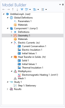
Definitions: Contains user-defined variables, selections, views, pairs, functions, probes, nonlocal couplings, and coordinate systems, which are defined locally for the model. See Global Definitions, Geometry, Mesh, and Materials for information about using these local Definitions () and Global Definitions (). Use Global Definitions to define Parameters, Variables, Functions, and loads and constraint groups with a global scope — that is, groups that are not specific to one Component node.
Geometry (): Contains the sequence of geometric objects and operations (or imported CAD data) that defines the model geometry.
Materials (): Contains the materials and material properties used as sources for material data in the component. See Materials for detailed information.
Physics interfaces (): Any added physics interface displays as a node under Component (Solid Mechanics in Figure 3-1 for example).
Multiphysics (): When a multiphysics interface is added to the Model Builder, this node contains all the relevant multiphysics coupling features for that interface. See Multiphysics Modeling Workflow for more information.
Meshes (): Contains the sequences of meshing operations that defines the computational meshes for the model. When there is only one mesh in the model, its Mesh node appears directly under the Component node.
The Settings window has the following sections (also see Figure 3-3):
The label appears on the node as the default node name. The default label is Component 1, but you can change it in the Label field.
The name is a string used to define a namespace for the model component and identify variables defined in that component. The default component name is comp1, comp2, and so on, but you can change it in the Name field. See Settings and Properties Windows for Feature Nodes and Displaying Node Names, Tags, and Types in the Model Builder for more information.
Unit System
The default setting in the Unit system list — Same as global system (SI) if the global unit system is the SI unit system — is to use the global unit system, which you specify in the root node’s Settings window. The global unit system appears in parentheses. If you want to use another unit system in a component, select it from this list. The unit system in the list that is used as the global unit system appears as, for example, SI (global system); that is, the information that it is the global system is appended to the unit system’s name.
Frames
In this section, you can define the coordinates for the frames in a model component if you do not want to keep the default names. All frames are always defined. See About Frames for more information about frames.
Spatial frame coordinates
For Spatial frame coordinates, the default names are x, y, and z for 3D as well as planar 1D and 2D geometries. For axisymmetric geometries, the default names for the spatial frame coordinates are r, (phi), and z. If you use the geometry to represent something other than space, or if you for some other reason want to use other names for the spatial coordinates, you can change the names in the fields for the First, Second, and Third coordinate under Spatial frame coordinates.
Material frame coordinates
For Material frame coordinates, the default names are X, Y, and Z for 3D as well as planar 1D and 2D geometries. For axisymmetric geometries, the default names for the material frame coordinates are R, (PHI), and Z. You can change the names in the fields for the First, Second, and Third coordinate under Material frame coordinates.
Geometry frame coordinates
For Geometry frame coordinates, the default names are Xg, Yg, and Zg for 3D as well as planar 1D and 2D geometries. For axisymmetric geometries, the default names for the geometry frame coordinates are Rg, (PHIg), and Zg. You can change the names in the fields for the First, Second, and Third coordinate under Geometry frame coordinates.
Mesh frame coordinates
For Mesh frame coordinates, the default names are Xm, Ym, and Zm for 3D as well as planar 1D and 2D geometries. For axisymmetric geometries, the default names for the mesh frame coordinates are Rm, (PHIm), and Zm. You can change the names in the fields for the First, Second, and Third coordinate under Mesh frame coordinates.
You cannot use the variable for the time, t, as a frame coordinate name.
If you have opened a model originally created in version 5.2 or earlier, click the Permanently Define All Frames button to, for example, enable the possibility to use a deformed geometry manually.
Curved Mesh Elements
Geometry Shape Function
The setting in the Geometry shape function list determines the shape function and order of the curved mesh elements that determine the geometry shape. The default setting is Automatic, but it is also possible to select one of the following geometry shape functions: Linear Lagrange, Quadratic Lagrange, Cubic Lagrange, Quartic Lagrange, Quintic Lagrange, Sextic Lagrange, Septic Lagrange, Linear serendipity, Quadratic serendipity, Cubic serendipity, or Quartic serendipity. The default setting allows for automatic reduction of the order in some cases. For a model with a single physics interface, the geometry shape function is usually the same as the discretization shape function for the physics field as long as the default setting, Automatic, is used. This setting ensures isoparametric elements.
By default, the software avoids inverted elements by an optimization of the element shapes. To deactivate that functionality, clear the Avoid inverted elements by curving interior domain elements check box. See Avoiding Inverted Mesh Elements for more information.
Geometric Model
This section is only available if there is at least one meshing sequence which defines its own geometric model. A meshing sequence that defines its own geometric model typically includes one or several mesh Import nodes (see Importing Meshes).
Use the setting Physics defined on to specify on which geometric model the physics is defined. It can be either the geometry sequence or a meshing sequence which defines its own geometric model. Meshes conforming with the geometry will not be available in the list. The geometry or meshing sequence selected here will be indicated with a green or yellow frame around its icon ( or ).