|
|
To create a helix with a noncircular cross section, define the cross section using a work plane. Define the helix centerpoint as a 3D curve using a Helix node with a minor radius = 0 or a Parametric Curve node, and then use a Sweep node to sweep the cross section from the work plane along the curve to create the helix.
|
|
•
|
The Major radius (SI unit: m) field is the radius from the center of the helix (the default is 1 m).
|
|
•
|
The Minor radius field (SI unit: m) is the radius of the cross section (the default is 0.1 m). The Minor radius can be zero, in which case a curve object is created. You can use this together with the Sweep feature to create helices with noncircular cross sections.
|
|
•
|
The Axial pitch field (SI unit: m) determines the axial distance between similar positions on two consecutive turns of the helix (the default is 0.3 m).
|
|
•
|
The Radial pitch field (SI unit: m) determines the radial distance between similar positions on two consecutive turns of the helix (the default is 0, which means that each turn has the same radius).
|
|
•
|
Select Parallel to axis (the default) to create end caps that are parallel to the helix axis.
|
|
•
|
Select Perpendicular to axis to create end caps that are perpendicular to the helix axis.
|
|
•
|
Select Parallel to spine to create end caps that are parallel to the spine of the helix.
|
|
•
|
Select x-axis, y-axis, or z-axis (the default) to define the axis direction parallel to one of the coordinate axes.
|
|
•
|
Select Cartesian to define the axis direction using Cartesian coordinates in the x, y, and z fields. The default axis is in the z direction (0, 0, 1).
|
|
•
|
Select Spherical to define the axis direction using spherical coordinates θ and
|
|
|
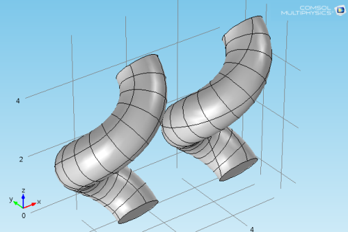
Twist compensation affects the position of the vertices on the top side of the helix. Clear the Twist compensation check box to turn it off. See Figure 7-6 below.
|